Hardware
Contents
General
It is possible to control the BMT Controller directly without any computer adding a keyboard and mouse at the USB port and a display at the HDMI port.
Back side
| 3.3 VDC output (1) | Bottom GND, Top 3.3 VDC
Suitable male connectors: Wurth Electronic Inc. part no. 662002113322 (Wurth Electronic Inc. terminals AWG 24-20 – part no. 66200113722DEC) |
| 5.0 VDC output (2) | Bottom GND, Top 5.0 VDC
Suitable male connectors: Wurth Electronic Inc. part no. 662002113322 (Wurth Electronic Inc. terminals AWG 24-20 – part no. 66200113722DEC) |
| I2C connection 3.3V Bus (3, 4) | 2 female connections
DC-Controller: GND, SDA, SCL (from left to right) Stepper- & Piezo-Controller: GND, SCL, SDA (from left to right) Suitable male connectors: Wurth Electronic Inc. part no. 662003013322 (Wurth Electronic Inc. terminals AWG 24-20 – part no. 66200113722DEC) |
| Input Voltage (5) | 24 VDC with max. 40 W
AC/DC adaptor included |
Front side
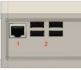
| LAN (1) | Gbit-LAN |
| USB (2) | 4 pcs. USB 2.0 ports |
| LED 1 | Status LED |
| LED 2 | Status LED |
| LED 3 | Status LED: On when BMT Controller is ready |
Left side
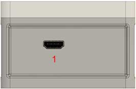
| HDMI or MINI-HDMI (1) | HDMI output |
Right side
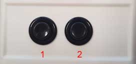
| Button (1) | Stop all ports
Pressed more than 3 seconds: Start program from USB Stick |
| Button (2) | Pressed less than 3 seconds: System rebooting
Pressed more than seconds: System shutdown |
BMT DC-Controller
| CAUTION: To prevent electric shock, unplug the system or turn the power off before adding a device. |
The available power is limited by the power supply with 1.5A and by the voltage converter with max. 3A each port. The internal computer power consumption depends on the connected peripheries and the load – average power consumption is around 6W.
| DC output up to 24VDC (PWM controlled) (1, 2, 3, 4, 5) | 5 female connections
24 VDC (PWM controlled), Bottom (GND) Top (24 VDC) – possible to change polarity LED indicates the operation. Suitable male connectors: Wurth Electronic Inc. part no. 662002113322 (Wurth Electronic Inc. terminals AWG 24-20 – part no. 66200113722DEC) |
| DC output up to 24VDC (PWM controlled), 3.3V PWM output, I2C output (6) | 1 female connection
24 VDC (PWM controlled), GND, 3.3 V (PWM controlled), SCL, SDA (from left to right) Suitable male connectors: Wurth Electronic Inc. part no. 662005013322 (Wurth Electronic Inc. terminals AWG 24-20 – part no. 66200113722DEC) |
The output voltage is PWM controlled and may has a tolerance of +/- 5%, for less than 6 VDC could the tolerance could be higher.
Polarity
Top connection port is "+", bottom port is "-".
BMT Stepper-Controller
| CAUTION: To prevent electric shock, unplug the system or turn the power off before adding a device. |
The output is current driven 0 – 440mA. (The voltage is for the internal driver chip and between 9 – approx. 16.7 VDC)
| Bipolar stepper output (1, 4) | 2 female connections
B2, B1, A2, A1 (from left to right) Example for (from left to tight) • RP-HX / Chip Pump: Yellow (B2)- Orange (B1) - Brown (A2) - Black (A1) • RP-TX: Yellow (B2)- Orange (B1) - Brown (A2) - Black (A1) LED indicates the operation. Suitable male connectors: Wurth Electronic Inc. part no. 662004013322 (Wurth Electronic Inc. terminals AWG 24-20 – part no. 66200113722DEC) |
| Sensor signal input 24VDC (2, 3) | 2 female connections
GND, Signal, 24VDC (from left to right) Suitable male connectors: Wurth Electronic Inc. part no. 662003013322 (Wurth Electronic Inc. terminals AWG 24-20 – part no. 66200113722DEC) |
The current output is PWM controlled and may has a tolerance of +/- 5%.
BMT Piezo-Controller
This controller is mainly designed to oparate the Takasago Electric piezo pumps: Takasago Piezo Pumps
| CAUTION: HIGH Output voltage (up to 340 Vp-p). To prevent electric shock, unplug the system or turn the power off before adding a device. |
| Piezo driver output (1, 2, 3, 4)
approx. 50 to 340 Vp-p 1 to 60 Hz (Takasago Standard Wave) |
4 female connections
LED indicates the operation. Suitable male connectors: Wurth Electronic Inc. part no. 662005013322 (Wurth Electronic Inc. terminals AWG 24-20 – part no. 66200113722DEC) |
The output voltage is PWM controlled and may has a tolerance of +/- 5%.
Note: Note all ports are equipped internally with piezo drivers.
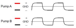
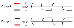
It is possible to run two pumps in parallel at one port:
| Phases | Operation timing |
|---|---|
| Same | Connect the red cable of pump A to the red cable of pump B, and the black of A to the black of B. The pumps suck and discharge at the same timing.
The pumps may not operate at exactly the same timing, as response to drive input varies from particular pump to pump. |
| Revers | Connect the red cable of pump A to the black cable of pump B, and the black of A to the red of B. The pumps suck and discharge at the reverse timing.
The pumps may not operate at exactly the same timing, as response to drive input varies from particular pump to pump. |
Referring Takasago MPD-200A manual.

