BMT DC-Controller
This controller allows to run DC-valves, DC-pumps and a Xavitech pump (at port 5) with a voltage between 0 and 24V DC – PWM controlled.
The DC Controller is designed and tested to be used with the BMT partner’s DC-Valves and DC-Pumps. On overview about the products can be found on our website: www.pumpen-ventile.de
Information about Hardware of DC-Controller.
| To prevent electric shock, unplug the system or turn the power off before adding a device. |
Contents
Run Programs
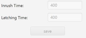
The settings of the holding time in milliseconds and the latching switch time in milliseconds are shown.
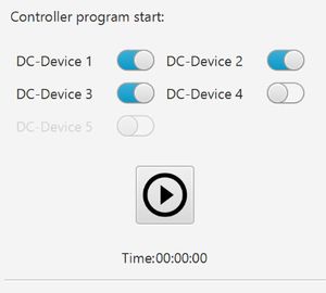
For every port where a program is added, it is possible to enable the program execution by enabling the switch at the port number.
If there is any enabled program, it is possible to start to run using the start button:
If there is a max. execution time for each program, the remaining time will be shown. The maximum number of all selected programs is used for this countdown. If there is any repeat endless program activation, there is an endless symbol.
Port Content
For each port of the DC-Controller the control function can be selected:
After selecting the configuration, the specific view is loaded. Changing this selection will stop the port and reloads the new configuration.
For the DC-Controller the following selection is available:
Valve
The configuration view allows to switch valves up to 24VDC, also using holding voltage to reduce power consumption and heat generation if needed. It is also possible to switch latching valve by changing the polarity for switching.
Board Details
Functions
Manual Control
| Name | Description |
|---|---|
| Voltage | Voltage can be selected using Preselection with common values like:
or manually by entering a value between 0 and 24 VDC. After changing the voltage, the port will be stopped. Wrong voltage settings may damage the connected device. |
| Holding voltage | Using holding voltage, the valve at this port will be switched with full voltage for the time configured as “Holding Time”, after this time, the voltage is reduced to 50%.
The holding time is in milli seconds. It is only possible to use either the holding voltage or the latching function. |
| Latching | This function allows to use this port running a latching valve. After the configured “Latching Time”, the valve switch signal will be turned off. Switching the valve again will change the polarity of the switching signal of this port for the latching time duration.
It is only possible to use either the latching function or the holding voltage. |
| Switch | This toggle button switches the valve state between ON and OFF.
Get sure that the connected valve is suitable for the voltage configuration. |
Program Control
| Name | Description |
|---|---|
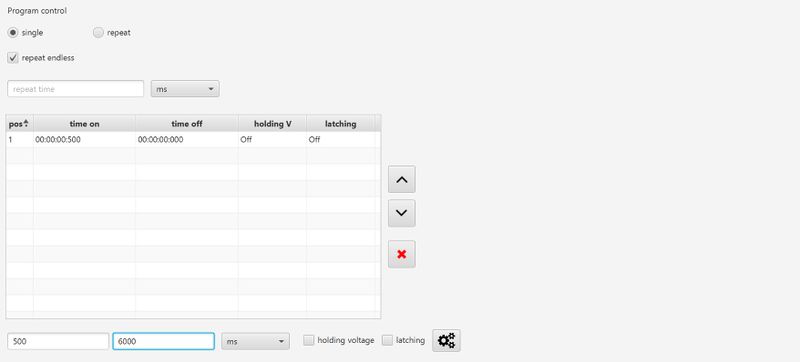
| single | The functions of the program table will be run once. |
| repeat | The functions of the program table will be repeated. |
| repeat endless | The repeating is endless and will only be stopped when the exception is stopped using the program stop button in the controller or program details. |
| repeat time | The program table will be repeated for the time entered in this field. |
| Program table | This table shows the configuration of the different program steps.
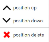
It is possible to re-order or delete the entries using the buttons at the right of the table, or the table menu using the right mouse klick. |
| Switching entry | Each program step can be configured using the entries:
Save the data to the table using the save button: |
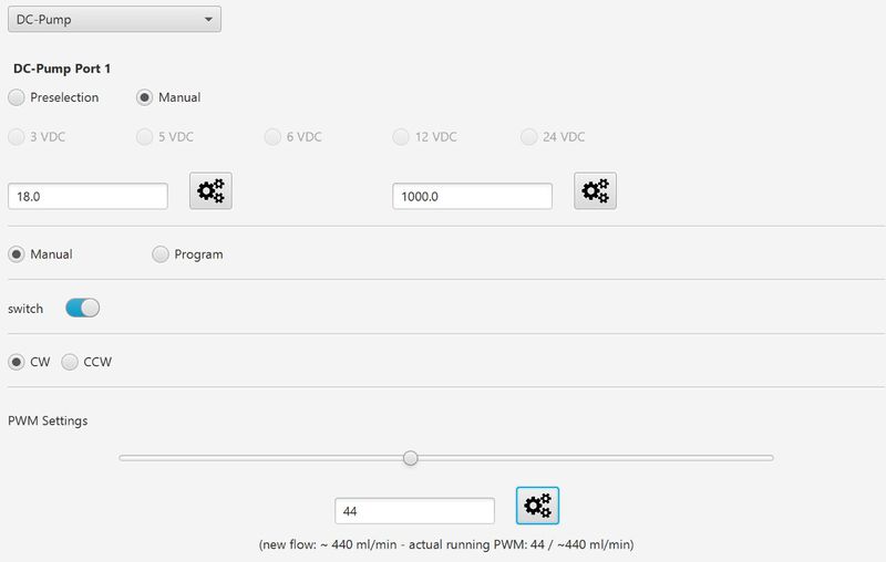
DC-Pump
The configuration view allows to run DC-pumps up to 24VDC. The output voltage can be set individually each port and additionally controlled using PWM. It is possible to change the polarity of the output voltage to run the pumps in both directions if the pump allows this function.
Functions
Manual Control
| Name | Description |
|---|---|
| Voltage | Voltage can be selected using Preselection with common values like:
or manually by entering a value between 0 and 24 VDC. After changing the voltage, the port will be stopped. Wrong voltage settings may damage the connected device. |
| Max. Flow | The max flow of this pump in ml/min.
This entry is used for calculating the roughly flow rate using the PWM value. This calculation can only be used as orientation and is not accurate! |
| switch | This toggle button switches the pump output voltage state between ON and OFF.
Get sure that the connected pump is suitable for the voltage configuration. |
| CCW | This selection changes the polarity of the pump.
By changing the polarity, the motor may change the operation direction. |
| PWM Settings | The slider changes the PWM setting in the text field of the PWM value. It is also possible to change the PWM number in the text field directly.
The new PWM value needs to be sent to the controller using the configuration button: |
Program Control
| Name | Description |
|---|---|
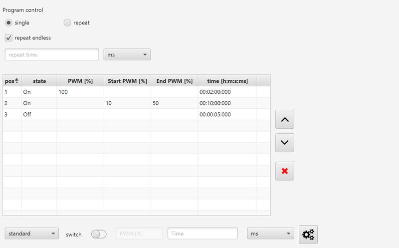
| single | The functions of the program table will be run once. |
| repeat | The functions of the program table will be repeated. |
| repeat endless | The repeating is endless and will only be stopped when the exception is stopped using the program stop button in the controller or program details. |
| repeat time | The program table will be repeated for the time entered in this field. |
| Program table | This table shows the configuration of the different program steps.
It is possible to re-order or delete the entries using the buttons at the right of the table, or the table menu using the right mouse klick. |
| standard program | Using the standard program configuration, the pump can be stopped or run with a specific PWM value and direction for a certain time using the entry values:
Save the data to the table using the save button: |
| Rise up/down program | The rise up or down configuration allows to linear reduce or increase the PWM signal from a start point to an endpoint over a given time:
Save the data to the table using the save button: |
Xavitech-Pump
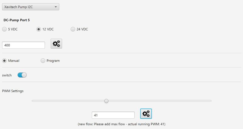
The configuration view allows to run the XAVITECH BLACK EDITION pumps with 5VDC, 12VDC and 24VDC. The I/O signal line can be used to control the PWM.
Manual Control
| Name | Description |
|---|---|
| Voltage | Voltage can be selected using Preselection with common values like:
After changing the voltage, the port will be stopped. Wrong voltage settings may damage the connected device. |
| Max. Flow | The max flow of this pump in ml/min.
This entry is used for calculating the roughly flow rate using the PWM value. This calculation can only be used as orientation and is not accurate! |
| switch | This toggle button switches the pump output voltage state between ON and OFF.
Get sure that the connected pump is suitable for the voltage configuration. |
| PWM Settings | The slider changes the PWM setting in the text field of the PWM value. It is also possible to change the PWM number in the text field directly.
The new PWM value needs to be sent to the controller using the configuration button: |
Program Control
| Name | Description |
|---|---|
| single | The functions of the program table will be run once. |
| repeat | The functions of the program table will be repeated. |
| repeat endless | The repeating is endless and will only be stopped when the exception is stopped using the program stop button in the controller or program details. |
| repeat time | The program table will be repeated for the time entered in this field. |
| Program table | This table shows the configuration of the different program steps.
It is possible to re-order or delete the entries using the buttons at the right of the table, or the table menu using the right mouse klick. |
| standard program | Using the standard program configuration, the pump can be stopped or run with a specific PWM value and direction for a certain time using the entry values:
Save the data to the table using the save button: |
| Rise up/down program | The rise up or down configuration allows to linear reduce or increase the PWM signal from a start point to an endpoint over a given time:
Save the data to the table using the save button: |

