BMT Stepper-Controller
This controller allows to run stepper motor driven pumps up to 1/128 micro steps driven by current between 0 and 440 mA. A 24 VDC sensor input as homing signal is used to drive syringe pumps.
Information about Hardware of Stepper-Controller.
| To prevent electric shock, unplug the system or turn the power off before adding a device. |
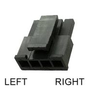
Cable connection stepper pumps
From left to right: A, A', B', B
The Stepper-Pump Controller is designed and tested to be used with the BMT partner’s Stepper-Pumps. Tested products are for example:
- RP-Q-B - Settings: RP-QB Settings
- RP-Q-C - Settings: RP-QC Settings
- RP-HX - Settings: RP-HX Settings
- RP-TX - Settings: RP-TX Settings
- Chip pump - Settings: QCP-29-Chippump Settings
Run Programs
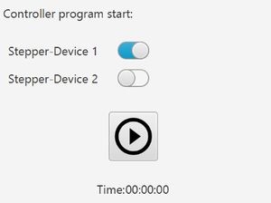
For every port where a program is added, it is possible to enable the program execution by enabling the switch at the port number.
If there is any enabled program, it is possible to start to run using the start button:
If there is a max. execution time for each program, the remaining time will be shown. The maximum number of all selected programs is used for this countdown. If there is any repeat endless program activation, there is an endless symbol.
Port Content
Select the connected device type. (Maybe other types are added in future)
Stepper Motor Pump
Pump Configuration
For each of these types the configuration of a pump needs to be selected, too.
This configuration can be edited or new pump configurations can be added for the pumps using this button.
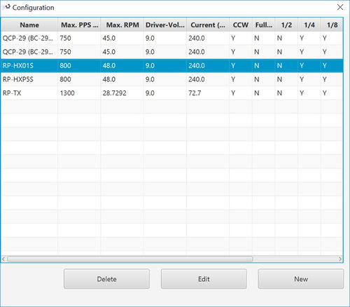
Pump configuration list
The new window will show a list with all pump configurations.
| Delete | This button deletes the selected pump entry in the table.
It is not possible to undo this action. If there is no table selection, this button is deactivated. |
| Edit | This button will open the edit view for the selected pump configuration in the table.
If there is no table selection, this button is deactivated. |
| New | This button will open the edit view to add a new pump configuration- |
Pump configuration view
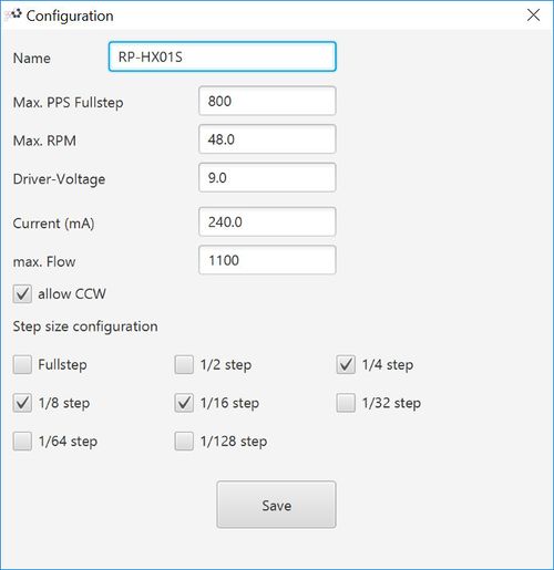
This view allows to edit or add a new pump configuration.
| Name | Name of the pump for selection. |
| Max. PPS Fullstep | The maximum pulse per seconds the pump allows at full step. |
| Max. RPM | The maximum rounds per minute for this pump. |
| Driver-Voltage | The voltage used for the stepper driver. |
| Current (mA) | The current output for the pump in mA. |
| max. Flow | The maximum flow for this pump.
(This entry is optional) |
| Step size configuration | Selecting the step sizes allowed to use for this pump. |
| Save | This button saves the changes or adds the new pump configuration.
After changing any details, the “Main Controller View” will be reloaded. The new settings will be updated directly for any new communication with the controller. |
| Any wrong values may damage the connected device by selecting the pump configuration for usage. |
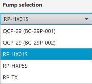
Pump Selection
Select a pump from the pump configuration – see chapter Pump Configuration.
| Any wrong selection may damage the connected device, due to the wrong output signals from the Pump Configuration. |
Functions
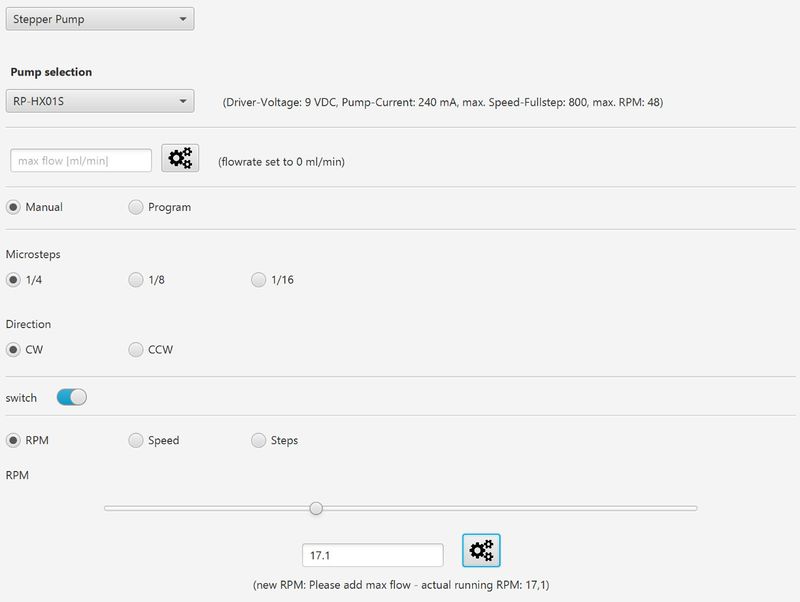
Manual Control
| Name | Description |
|---|---|
| Max. Flow rate | The max flow of this pump in ml/min.
This entry is used for calculating the roughly flow rate using the PPS/RPM value. This calculation can only be used as orientation and is not accurate! |
| Microsteps | The step size the pump will be operated with using RPM, PPS or Steps. Depending on the activation of the selected pump configuration, following options are possible:
|
| Direction | This selection changes the direction of the pump driver signal.
This selection is only visible if the pump configurations allows the usage. |
| switch | This toggle button switches the pump output voltage state between ON and OFF.
Get sure that the connected pump is suitable for the current configuration. |
Manual Control - RPM
The slider changes the RPM setting in the text field of the RPM value. It is also possible to change the RPM number in the text field directly. The value can be between 0 and the max. RPM – calculated from “max. RPM”, the “max. PPS Fullstep” of the pump configuration setting and the selected microstep value.
The new RPM value needs to be sent to the controller using the configuration button:
Manual Control - Speed
The slider changes the PPS setting in the text field of the PPS value. It is also possible to change the PPS number in the text field directly. The value can be between 0 and the max. PPS – calculated from “max. PPS Fullstep” of the pump configuration setting and the selected microstep value.
The new PPS value needs to be sent to the controller using the configuration button:
Manual Control - Steps
The slider sets the PPS Setting between 0 and 500 PPS. The number of steps can be set in the text field.
After starting the step control using the configuration button:
The pump will start to run the number of steps using the speed with the selected PPS. After reaching the given number of steps, the pump will stop.
Note: The PPS speed is run by software and not strictly accurate. This mode should be used for specific step operation.
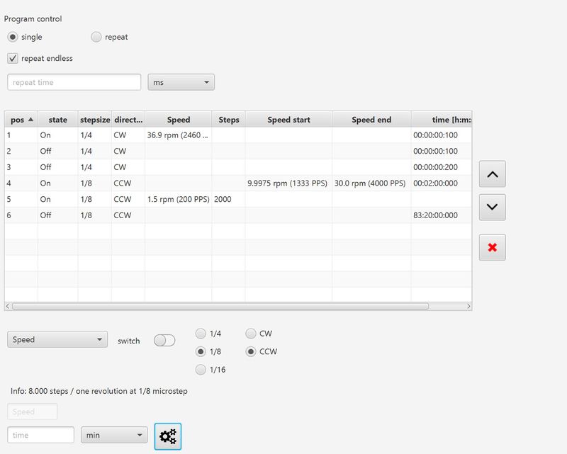
Program Control
| Name | Description |
|---|---|
| single | The functions of the program table will be run once. |
| repeat | The functions of the program table will be repeated. |
| repeat endless | The repeating is endless and will only be stopped when the exception is stopped using the program stop button in the controller or program details. |
| repeat time | The program table will be repeated for the time entered in this field. |
| Program table | This table shows the configuration of the different program steps.
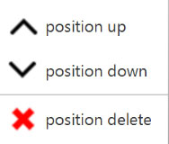
It is possible to re-order or delete the entries using the buttons at the right of the table, or the table menu using the right mouse klick. |
| RPM control | Using the RPM program configuration, the pump can be stopped or run with a specific RPM value and direction for a certain time using the entry values:
Save the data to the table using the save button: |
| Speed control | Using the PPS program configuration, the pump can be stopped or run with a specific PPS value and direction for a certain time using the entry values:
Save the data to the table using the save button: |
| Steps control | Using the steps program configuration, the pump can be run for a certain number of steps with a given PPS speed and direction for a certain time using the entry values:
Save the data to the table using the save button: |
| Steps control | The rise up or down PPS configuration allows to linear reduce or increase the PPS signal from a start point to an endpoint over a given time:
Save the data to the table using the save button: |
| Steps control | The rise up or down RPM configuration allows to linear reduce or increase the RPM value from a start point to an endpoint over a given time:
Save the data to the table using the save button: |

